Pressure and Fluid Statics: Hydraulic Lift (Pascal’s Law)
Pascal’s Principle
| Pascal's Principle | Our Hydraulic Lift |
|---|---|
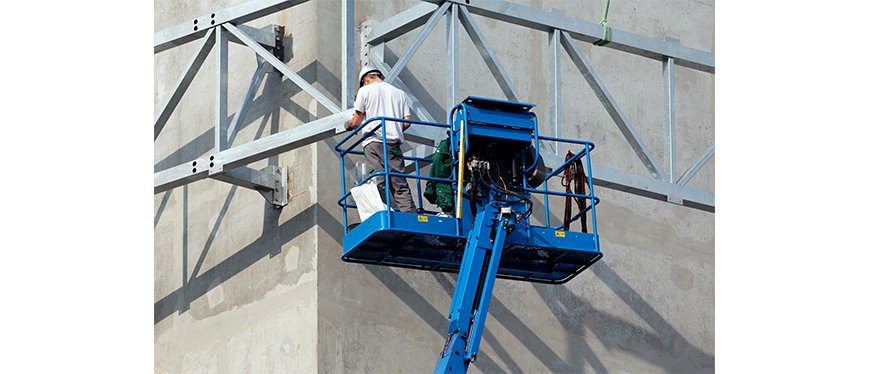
Pascal’s Principle is applied to numerous applications in daily life. Cars alone utilize Pascal’s Principle in many of the subsystems. If you had to directly apply the required force to stop a car using your foot, you would not be able to. Hydraulic braking systems use Pascal’s Principle to gain mechanical advantage and allow a smaller force input to equal a larger output force. This also applies to elevators, heavy machinery, and car lifting mechanisms as well. | 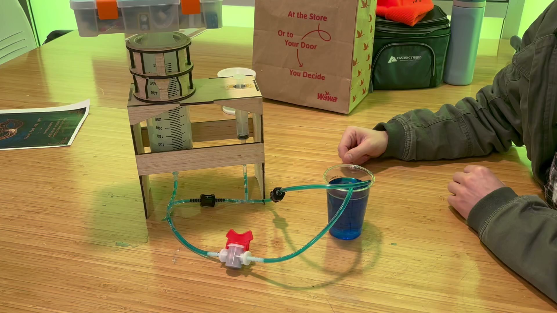 |
 Lift System [4] |  Auto Lift [3] | 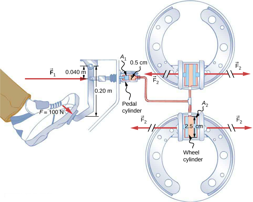 Force Diagram [1] |
Pascal’s Principle: In a fluid at rest in a closed container, a pressure change in one part is transmitted without loss to every portion of the fluid and to the walls of the container.
Essentially, when a force over an area is applied to a fluid in the container, assuming you are dealing with an incompressible fluid at normal conditions, the pressure is applied everywhere in the container and on the fluid in the container. [2]
Project Description
To demonstrate Pascal’s Principle, we have created a hydraulic lift which allows you to apply a relatively smaller force to lift a heavy object relying on mechanical advantage. We have utilized syringes with differing cross-sectional areas to gain mechanical advantage to lift a heavy object pushing down on the small syringe.
Mathematically, this can be seen in the two equations below:
Assuming would be your lighter object with a small , and would be your larger object with a larger cross-sectional area , the force applied to would be equal to the applied multiplied with the ratio of the two cross-sectional areas (also known as your mechanical advantage).
Video of Final Project
Materials
While these links are for amazon.com, feel free to purchase the materials anywhere.
| Item | Quantity (Required) | Image of Part | Link | Price |
|---|---|---|---|---|
| Ball Valve 5/32 OD (2 Pack) | 1 | 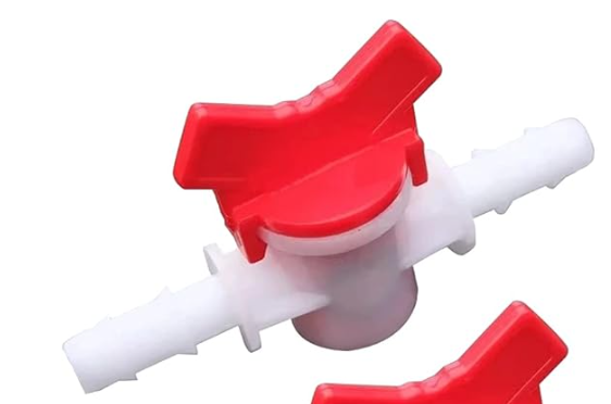 | Part | $7.99 |
| Check Valve 5/32 OD (2 Pack) | 1 | 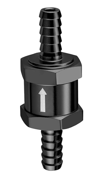 | Part | $9.99 |
| Large Syringe 500mL | 1 | 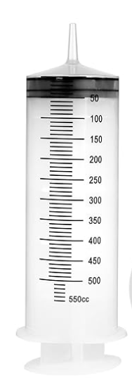 | Part | $10.99 |
| Small Syringe 20mL (3 pack) | 1 | 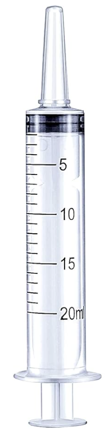 | Part | $4.99 |
| T-Connector 5/32 OD (5 pack) | 2 | 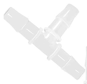 | Part | $6.99 |
| Acrylic Tubing (ID 5/32) | 10ft | 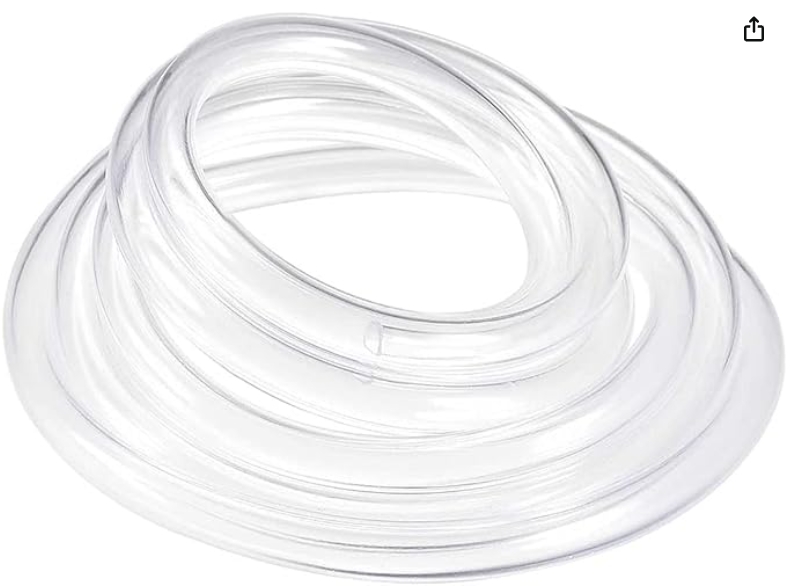 | Part | $8.99 |
| Total Price | $49.94 |
CAD Files
 | 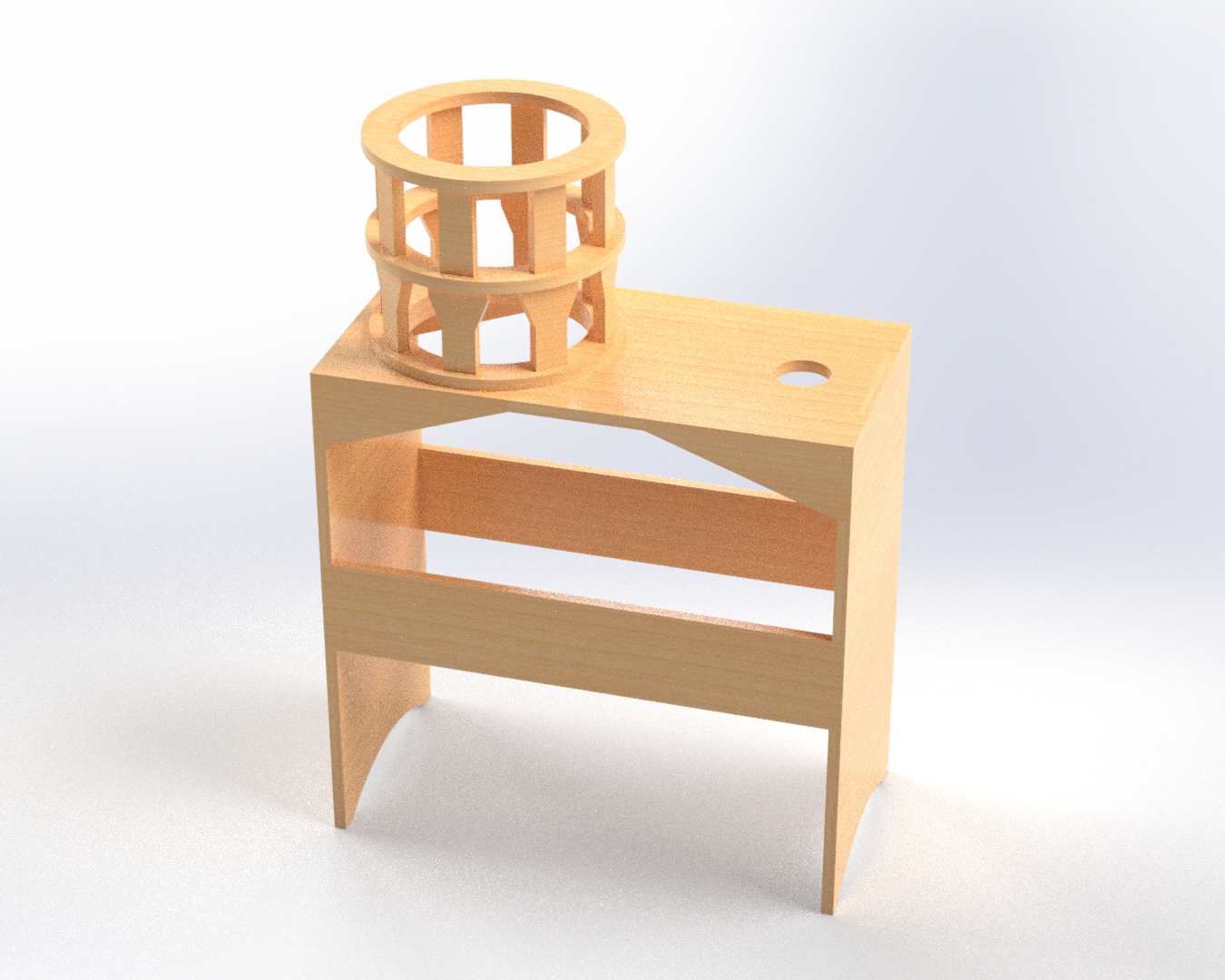 |
All of the parts shown in the zip folder were made using a laser cutter.
Construction / Assembly Details
Cut 5 pieces of acrylic tubing at ~2 inches long.
Cut 3 ~1ft long segments of acrylic tubing (2 of these will connect to the reservoir).
Fit T-connector “A” with 3, 2 inch acrylic tubing.
Fit T-connector “B” with 2, 2 inch acrylic tubing and a 1ft long piece of acrylic tubing. Prioritize the 1ft piece on either long ends and NOT the center adapter.
On the intake side of check valve “A”, connect a 1 ft piece of tubing.
On the opposite side of check valve “A”, connect it to T-connector “A” on either of the long ends.
Connect the 20mL syringe to the top center adapter of T-connector “A”.
Connect check valve “B” to the last point on T-connector “A”. Make sure both arrows on the check valves are facing the same direction and in a straight line (towards the large syringe).
Connect check valve “B” to the center of T-connector “B”.
Connect the 500mL syringe to the long side of T-connector “B”.
Connect the manual ball valve to the 1 ft acrylic tubing on T-connector “B”.
On the outlet of the ball valve, connect a 1ft piece of acrylic tubing that will attach to the reservoir.
Submerge both 1ft pieces of tubing coming out from check valve “A” and the ball valve into a cup to begin the demonstration.
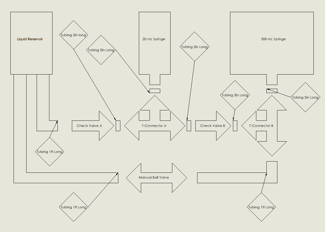
SolidWorks Drawing of Pipe Network
Experiment Results
Small syringe diameter: 0.725 in
Large syringe diameter: 2.615 in
Mechanical Advantage:
Math Questions
With mechanical advantage of 13, how much input force (in lbf) is required to lift 180lbf?
Answer
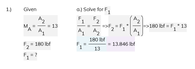
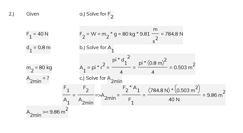
You can apply a 40N force on the left side piston in the system. The left side piston has a diameter of 0.8m, and the object on it has a mass of 80kg. What is the minimum area needed on the right piston to be able to lift the box?
Answer
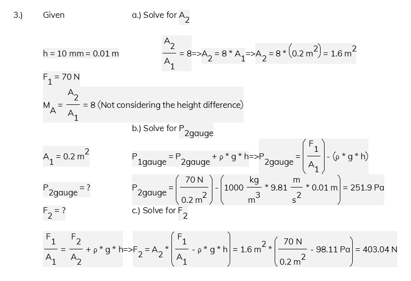
A force of 70N is applied to the lower height piston. If you have a J shaped tube with pistons on each end, with a height difference of 10mm, a mechanical advantage of 8 (not taking into account the height difference), cross-sectional area of the lower piston of 0.2m^2, what is the gauge pressure on the piston that is higher up? What is the force of the object on the higher up piston?
Answer
Conceptual Questions
If the diameter of one side changes by a factor of 2, how much more force is required to lift the object?
Answer
4 times more force.
If the heights of the tube were different, would that affect the output force?
Answer
When the tubes have a small height difference, you can ignore the pressure difference, but if the tubes have a significant pressure difference, you would need to calculate the pressure using the added pressure of the fluid height difference.
What needs to be considered to use a hydraulic lift under water?
Answer
Water leaking into the pistons, buoyancy forces, and different atmospheric pressure (not air).
Conclusion
This model demonstrates the use of Pascal’s Law with a hydraulic pump. The difference in cross-sectional area between the small and large syringe will provide a mechanical advantage. This advantage will allow the user to lift a heavier object with the large syringe while using less force with the small syringe. The use of check valves ensures that the liquid used will travel in one direction. The ball valve can be manually opened or closed depending on the progression of the demonstration. Close the valve to initiate the demonstration. Open the valve to release the pressure, allowing the large syringe to compress down. When calculating the force you apply to the amount the object moves, there will be losses. These losses are because of air in the tubing, change in cross-sectional areas of the T-connectors, leaking of the tubing at the connections, and other factors related to frictional losses.
References
[1] 11.5 pascal’s principle. 11.5 Pascal’s Principle | TEKS Guide. (n.d.). https://
[2] Britannica. (n.d.). Pascal’s principle | definition, example, & facts | britannica. Pascal’s principle. https://
[3] Spoa10-AV. Rotary Solutions. (2026, April 16). https://
[4] Whyps. (2023, November 23). How do hydraulic lifts work. https://